Setup → Boundaries

Purpose · Steps · Inputs and units · Limitations · Related topics

Purpose

Assign flow and thermal conditions to the boundary patches of the mesh.

Steps

  1. Open Boundaries and select a category or listed patch to display its settings.
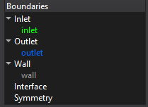
    Boundaries controls

  2. Select the required patch and boundary type, then enter the flow values and any enabled turbulence or thermal values.
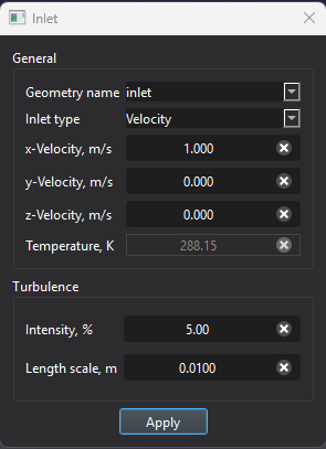
    Boundaries controls

  3. For prescribed wall heating, select Heat flux in the thermal settings and enter the signed flux. Apply the changes.
  4. For a CHT interface, review the paired interface and select the required thermal contact condition. Check patch assignments in the Setup view.

Inputs and units

Input or valueMeaningUnits
Velocity / mass flowValues required by the selected inlet condition.m/s and kg/s; ft/s and lb/s
Pressure / temperatureUse the pressure convention and values indicated in the boundary dialog.Pa and K; psi and °F
Heat fluxPositive values heat the domain; negative values cool it.W/m²; BTU/(h·ft²)
Thermal contactPerfect contact or resistance for supported interfaces.Use the interface field label

Limitations

All help topics